- 您现在的位置:买卖IC网 > Sheet目录475 > MAX9985ETX+T (Maxim Integrated)IC MIXER DOWN CONV DUAL 36-TQFN
�� �
�
�MAX9985�
�Dual,� SiGe,� High-Linearity,� 700MHz� to� 1000MHz�
�Downconversion� Mixer� with� LO� Buffer/Switch�
�LO� Buffer� Bias� Resistors�
�Bias� currents� for� the� two� on-chip� LO� buffers� is� opti-�
�mized� by� fine-tuning� the� off-chip� resistors� on� LODBIAS�
�(pin� 17)� and� LOMBIAS� (pin� 29).� The� current� in� the�
�buffer� amplifiers� is� reduced� by� increasing� the� value� of�
�these� resistors,� but� performance� may� degrade.� See� the�
�Typical� Operating� Characteristics� for� key� performance�
�parameters� versus� this� resistor� value.� Doubling� the�
�value� of� these� resistors� reduces� the� total� chip� current�
�Power-Supply� Bypassing�
�Proper� voltage-supply� bypassing� is� essential� for� high-�
�frequency� circuit� stability.� Bypass� each� V� CC� pin� and�
�TAPMAIN/TAPDIV� with� the� capacitors� shown� in� the�
�Typical� Application� Circuit� (see� Table� 2� for� component�
�values).� Place� the� TAPMAIN/TAPDIV� bypass� capacitor�
�to� ground� within� 100� mils� of� the� pin.�
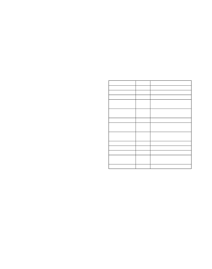
�Table� 2.� Component� Values�
�by� approximately� 50mA� (see� Table� 1).�
�IF� Amplifier� Bias� Resistors�
�Bias� currents� for� the� two� on-chip� IF� amplifiers� are� opti-�
�mized� by� fine-tuning� the� off-chip� resistors� on� IFDBIAS�
�(pin� 11)� and� IFMBIAS� (pin� 35).� The� current� in� the� IF�
�amplifiers� is� decreased� by� raising� the� value� of� these�
�resistors,� but� performance� may� degrade.� See� the�
�Typical� Operating� Characteristics� for� key� performance�
�parameters� versus� this� resistor� value.� Doubling� the�
�value� of� this� resistor� reduces� the� current� in� each� IF�
�amplifier� from� 100mA� to� approximately� 50mA� (see�
�Table� 1).�
�LEXT� Inductor�
�Short� LEXT_� to� ground� using� a� 0� ?� resistor.� For� applica-�
�tions� requiring� improved� RF-to-IF� and� LO-to-IF� isolation,�
�LEXT_� can� be� used� by� connecting� a� low-ESR� inductor�
�from� LEXT_� to� GND.� See� the� Typical� Operating�
�Characteristics� on� RF-to-IF� port� isolation� and� LO-to-IF�
�port� leakage� for� various� inductor� values.� The� load�
�impedance� presented� to� the� mixer� must� be� such� that�
�any� capacitance� from� both� IF-� and� IF+� to� ground� do�
�not� exceed� several� picofarads� to� ensure� stable� operat-�
�ing� conditions.�
�COMPONENT�
�C1,� C2,� C7,� C8�
�C3,� C6�
�C4,� C5�
�C9,� C13,� C15,�
�C17,� C18�
�C10,� C11,� C12,�
�C19,� C20,� C21�
�C14,� C16�
�L1,� L2,� L4,� L5�
�L3,� L6�
�R1,� R4�
�R2,� R5�
�R3,� R6�
�T1,� T2�
�U1�
�VALUE�
�39pF�
�0.033μF�
�—�
�0.01μF�
�150pF�
�82pF�
�560nH�
�30nH�
�1.07k� ?�
�1.1k� ?�
�0� ?�
�4:1�
�—�
�DESCRIPTION�
�Microwave� capacitors� (0402)�
�Microwave� capacitors� (0603)�
�Not� used�
�Microwave� capacitors� (0402)�
�Microwave� capacitors� (0603)�
�Microwave� capacitors� (0402)�
�Wire-wound� high-Q� inductors�
�(0805)�
�Wire-wound� high-Q� inductors�
�(0603)�
�±1%� resistors� (0402)�
�±1%� resistors� (0402)�
�Resistors� (1206)�
�Transformers� (200:50)�
�Mini-Circuits� TC4-1W-7A�
�MAX9985� IC�
�Approximately� 100mA� flows� through� LEXT_,� so� it� is�
�important� to� use� a� low-DCR� wire-wound� inductor.�
�Layout� Considerations�
�A� properly� designed� PCB� is� an� essential� part� of� any�
�RF/microwave� circuit.� Keep� RF� signal� lines� as� short� as�
�possible� to� reduce� losses,� radiation,� and� inductance.�
�For� the� best� performance,� route� the� ground� pin� traces�
�directly� to� the� exposed� paddle� under� the� package.� The�
�PCB� exposed� paddle� MUST� be� connected� to� the�
�ground� plane� of� the� PCB.� It� is� suggested� that� multiple�
�vias� be� used� to� connect� this� paddle� to� the� lower-level�
�ground� planes.� This� method� provides� a� good� RF/ther-�
�mal-conduction� path� for� the� device.� Solder� the� exposed�
�paddle� on� the� bottom� of� the� device� package� to� the�
�PCB.� Refer� to� the� MAX9985� Evaluation� Kit� as� a� refer-�
�ence� for� board� layout.� Gerber� files� are� available� upon�
�request� at� www.maxim-ic.com.�
�Maxim� Integrated�
�Exposed� Paddle� RF/Thermal�
�Considerations�
�The� exposed� paddle� (EP)� of� the� MAX9985’s� 36-pin� thin�
�QFN-EP� package� provides� a� low� thermal-resistance�
�path� to� the� die.� It� is� important� that� the� PCB� on� which� the�
�MAX9985� is� mounted� be� designed� to� conduct� heat�
�from� the� EP.� In� addition,� provide� the� EP� with� a� low-�
�inductance� path� to� electrical� ground.� The� EP� MUST� be�
�soldered� to� a� ground� plane� on� the� PCB,� either� directly�
�or� through� an� array� of� plated� via� holes.�
�13�
�发布紧急采购,3分钟左右您将得到回复。
相关PDF资料
MAX9985EVKIT#
KIT EVAL FOR MAX9985
MAX9986AETP+T
IC MIXER DOWN CONV 20-TQFN
MAX9986AEVKIT
EVAL KIT FOR MAX9986
MAX9986ETP+TD
IC MIXER DOWN CONV 20-TQFN
MAX9986EVKIT
EVAL KIT FOR MAX9986
MAX9987ETP+
IC BUFFER/SPLITTER LO 20-TQFN
MAX9988EVKIT
EVAL KIT FOR MAX9988
MAX9989ETP+T
IC BUFFER LO 20-TQFN
相关代理商/技术参数
MAX9985ETX-T
功能描述:上下转换器 SiGe 700-1000MHz Downconversion Mixer RoHS:否 制造商:Texas Instruments 产品:Down Converters 射频:52 MHz to 78 MHz 中频:300 MHz LO频率: 功率增益: P1dB: 工作电源电压:1.8 V, 3.3 V 工作电源电流:120 mA 最大功率耗散:1 W 最大工作温度:+ 85 C 安装风格:SMD/SMT 封装 / 箱体:PQFP-128
MAX9985EVKIT
制造商:Maxim Integrated Products 功能描述:DUAL SIGE HIGH-LINEARITY 700 - 1 - Rail/Tube
MAX9985EVKIT#
功能描述:射频开发工具 RoHS:否 制造商:Taiyo Yuden 产品:Wireless Modules 类型:Wireless Audio 工具用于评估:WYSAAVDX7 频率: 工作电源电压:3.4 V to 5.5 V
MAX9986AETP+
功能描述:上下转换器 SiGe 815-1000MHz Downconversion Mixer RoHS:否 制造商:Texas Instruments 产品:Down Converters 射频:52 MHz to 78 MHz 中频:300 MHz LO频率: 功率增益: P1dB: 工作电源电压:1.8 V, 3.3 V 工作电源电流:120 mA 最大功率耗散:1 W 最大工作温度:+ 85 C 安装风格:SMD/SMT 封装 / 箱体:PQFP-128
MAX9986AETP+T
功能描述:上下转换器 SiGe 815-1000MHz Downconversion Mixer RoHS:否 制造商:Texas Instruments 产品:Down Converters 射频:52 MHz to 78 MHz 中频:300 MHz LO频率: 功率增益: P1dB: 工作电源电压:1.8 V, 3.3 V 工作电源电流:120 mA 最大功率耗散:1 W 最大工作温度:+ 85 C 安装风格:SMD/SMT 封装 / 箱体:PQFP-128
MAX9986AEVKIT
功能描述:射频开发工具 RoHS:否 制造商:Taiyo Yuden 产品:Wireless Modules 类型:Wireless Audio 工具用于评估:WYSAAVDX7 频率: 工作电源电压:3.4 V to 5.5 V
MAX9986ETP
功能描述:上下转换器 SiGe 815-1000MHz Downconversion Mixer RoHS:否 制造商:Texas Instruments 产品:Down Converters 射频:52 MHz to 78 MHz 中频:300 MHz LO频率: 功率增益: P1dB: 工作电源电压:1.8 V, 3.3 V 工作电源电流:120 mA 最大功率耗散:1 W 最大工作温度:+ 85 C 安装风格:SMD/SMT 封装 / 箱体:PQFP-128
MAX9986ETP+
功能描述:上下转换器 SiGe 815-1000MHz Downconversion Mixer RoHS:否 制造商:Texas Instruments 产品:Down Converters 射频:52 MHz to 78 MHz 中频:300 MHz LO频率: 功率增益: P1dB: 工作电源电压:1.8 V, 3.3 V 工作电源电流:120 mA 最大功率耗散:1 W 最大工作温度:+ 85 C 安装风格:SMD/SMT 封装 / 箱体:PQFP-128